
Operating and maintenance instructions Gear unit
Important informations
Live parts, rotating parts and hot surfaces of electrical machines can cause serious injury or property damages.
Installation, connection, start-up and maintenance has to be performed by qualified personnel.
The safety instructions, the installation and maintanance instructions, the project documents and the relevant national, local and system specific safety requirements must be observed.
- We reserve the right to make changes of all informations provided from this program.
- Any damage found to have been caused during transport should be notified to the freight forwarder without delay.
- Damaged products must not be taken into operation.
- The observance of the installation and maintenance instructions is condition for safe operation and to fulfill warranty claims.
- The products may only be stored in closed, dry rooms, protected from mechanical damage and vibration, permissible ambient temperature for storage: 0…+60°C
In case of long-term storage, consultation with the manufacturer is necessary. - The lifting lugs provided have only be designed for the weight of the product, additional loads must not be attached.
These instructions are not meant to cover all details concerning any possible design and applications.
In case of doubt, contact the manufacturer!
Manufacturer:
KEB Antriebstechnik GmbH
Wildbacher Straße 5
08289 Schneeberg
Germany
Tel +49 3772 67-0
Fax +49 3772 67-281
E-Mail info@keb-drive.de
Service
If you need our service, please indicate the following:
- complete nameplate information
- detailed description of problem
- if possible, add digital images to the description
The identification of spare parts requires the nameplate data of the product with the manufacturers serial number.
Disposal note
Dispose the products properly and in compliance with local regulations
- Gears, shafts, bearings as steel
- Gear housing as aluminum or iron
- Worm wheels as non-ferrous metal
- Lubricants must be collected and disposed properly
- Motors as motor scrap ingredients aluminum, iron, copper, plastics
- Electronic components as electronic scrap
Mechanical installation
- Before mounting,remove the corrosion protection of the output shaft and grease the shaft surface
- Gearbox installation free of shock and tension
- Pay attention to alignment when using a coupling
- Oil vent-, control- and drain plug have to be accessible.
- Pay attention to proper gearbox aeration
When the gearbox is delivered with closed plug instead of vent plug: Change plug against supplied vent plug or pressure valve. - Check lubrication level according mounting position and name plate data
- Installation of gearbox in wet ambient or outdoors requires anticorrosive execution.
Touch up painting damages after installation. - Observe the tightening torque for mounting screws
| Screw/Nut | tightening torque [Nm] strength class 8.8 | use at Through Hole |
| M6 | 10 | Ø6.6 |
| M8 | 24 | Ø9 |
| M10 | 53 | Ø11 |
| M12 | 90 | Ø13.5 |
| M16 | 220 | Ø17.5 |
| M20 | 430 | Ø22 |
| M24 | 740 | Ø26 |
| M30 | 1490 | Ø33 |
| M36 | 2600 | Ø39 |
Output shaft with key
Mounting of couplings or driving elements by assembly tool
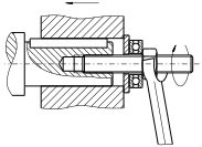
Example for assembly tool
- Use center hole of output shaft
Heat the transmission elements or use of lubricant simplify the assembly - Avoid shocks during mounting of transmission elements.
- Transmission elements has to be balanced.
- Fix the key at start without coupling.
During mounting of transmission element inadmissable loads are prohibited.
(e.g. to much tension of chain or belt, misalignment of coupling)
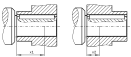
unfavorable position favorable position
Hollow shaft with keyway
- Use assembling tool for mounting
- Protect the connection against corrosion by proper lubricants
Assembly / Disassembly notes when using gear units with hollow shaft
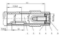 Assembly on shaft with shoulder Length of customers shaft: L1-1mm |
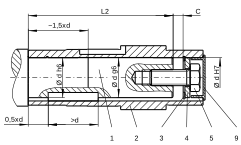 Assembly on shaft with shoulder Disassembly with turn safe nut possible Length of customers shaft: L2 |
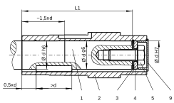 Assembly on shaft without shoulder Length of customers shaft: L1 |
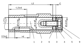 Assembly on shaft without shoulder Disassembly with turn safe nut possible Length of customers shaft: L2 |
| Gear unit | d | L1 | L2 | C | C1 | C2 | E1 | M | T | U |
| S0 | 20 | 76 | 64 | 12 | 5 | 6 | 19.7 | M6 | 22.5 | 5.5 |
| K0 | 20 | 91 | 79 | 12 | 5 | 6 | 19.7 | M6 | 22.5 | 5.5 |
| S1, F2, K1, K2 | 25 | 105 | 89 | 16 | 5 | 10 | 24.7 | M10 | 28 | 7.5 |
| S2, F3, K3 | 30 | 132 | 116 | 16 | 5 | 10 | 29.7 | M10 | 33 | 7.5 |
| S2, F3, K3 | 35 | 132 | 116 | 16 | 5 | 10 | 34.7 | M12 | 38 | 9.5 |
| S3, F4, K4 | 40 | 155 | 137 | 18 | 5 | 12 | 39.7 | M16 | 43 | 11.5 |
| S4, F5, K5 | 50 | 185 | 167 | 18 | 5 | 12 | 49.7 | M16 | 53.5 | 13.5 |
| F6, K6 | 60 | 210 | 188 | 22 | 5 | 16 | 59.7 | M20 | 64 | 17.5 |
| F7, K7 | 70 | 270 | 248 | 22 | 5 | 16 | 69.7 | M20 | 74.5 | 19.5 |
| F8, K8 | 90 | 315 | 289 | 26 | 5 | 20 | 89.7 | M24 | 95 | 24.5 |
| K9 | 100 | 375 | 349 | 26 | 5 | 20 | 99.7 | M24 | 106 | 27.5 |
1 Customer's shaft
2 Hollow shaft
3 Circlip DIN472
4 Washer
5 Screw DIN933
6 Spacer
7 Washer
8 Nut with tang
9 Closing cap
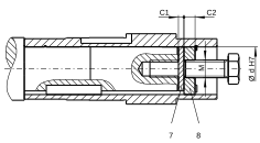
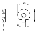
assembly kit for hollow shaft with keyway: Parts 3,4,5,9
Hollow shaft with shrink disc
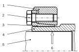
1 outer ring
2 tension screw
3 inner ring
4 hub
5 Shaft
6 free of grease
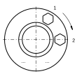
assembling
- shrink discs are ready for installation
Do not dismantle the unit before bracing the first time. - Degrease the hub bore and shaft.
- Install the shrink disc on shaft
- the outside surface of shrink disk hub can be protected by grease.
Tighten the tension screws after installation of shaft only - Fit the shaft or install the hub on shaft. Tighten of tension screws even allocated, untill aligning of lateral front face of inner and outer ring
-
Observe the tightening torque of tension scews from shrink disk!
tension screw M6 M8 M10 M12 M14 Tightening torque Ma [Nm] 12 30 59 100 160 - Do not disassemble dismanteled shrink disc before installation once again.
clean and grease shrink disc after contermination only
Use solid material lubricant with friction coefficient of µ=0.04 (e.g. Molykote Spray)
Startup
- Before startup, check correct mounting position and lubrication level of the gearbox
- Startup of worm gearboxes:
With new helical-worm gear units the tooth flanks are not completely smoothed down. The efficiency is lower than after the running in process.
For a two start worm the decrease is about 6%. The running-in process is essentially concluded after 24 hours.
Attachment of motors on input adapter
use supplied coupling only. Installation of coupling part flush to motor shaft end. Fixation of coupling part by grubscrew
Do not exceed the permitted forces Fmax in the table by weight or other forces to avoid overload, deformations and inadmissible heating.
| - M IEC | - M NEMA | - M S | X [mm] | Fmax [N] |
| 63/71 | 56 | 70 | 80 | 450 |
| 80/90 | 140 | 90/110 | 120 | 800 |
| 100/112 | 180 | 140 | 140 | 1600 |
| 132 | 210 | 190 | 180 | 2000 |
| 160/180 | 250/280 | 230 | 4000 | |
| 200/225 | 290 | 6000 |
X: distance of emphasis from main machine to adapter flange
Fmax: permissable force at emphasis of main machine
increase of distance X causes linear reduction of Fmax
for decrease of distance X the value of Fmax remains constant
Inspection and maintenance
-
Oil level control in gearbox after each 1000 working hours, minimum after 6 month
Recommended change of lubricant depending on operation conditions.Mineraloil: Oil bath temperature <=60°C, to 10.000 hours of operation
Oil bath temperature <=80°C, to 5.000 hours of operation
after 2 years at latestSynthetic oil: Oil bath temperature <=80°C, to 10.000 hours of operation
Oil bath temperature <=100°C, to 5.000 hours of operation
after 5 years at latest - Check bearings at oil level control
Change when noise or temperature are increased
Feed roller bearings on output shaft (excluding mounting position M4) with grease with consistency class 2. - Check seal at sight depending on operation conditions after 1000 hours, minimum after 6 month for leaks
seal leaking gearboxes, if necessary add missing oil volume
Recommended change of seals: after 5 years at latest - Check screw connections for tightness
- Repair corrosion damages
Motor adapter -M IEC, -M NEMA
- Control the coupling between motor and gearbox for the first time after 3000 hours, latest after 6 months.
Visual inspection, backlash, wear measurement with feeler gauge between hub and the spider -
Reference data:
- M IEC - M NEMA s 63/71 56 2mm 80/90/100/112/132 140/180/210 3mm 160/180 250/280 4mm - if the values are exceeded, switch spider
with low wear, the inspection interval can be increased to 6000 hours/18 months
Check oil level / Change of lubrication
- Warm up of gearbox simplify drain of oil
Attention: danger that lubricant splashes from the gear unit - Before opening the drain plug or level plug: Remove filler plug to reduce existing pressure in the gear unit
- Fill only lubricant of type and volume shown on name plate
- Consider selection table for type of lubrication
- Make wearing check of worm-wheel at same time.
- Tightening torque for oil plugs / breather valves: M10x1-8Nm, M12x1.5-14Nm, M22x1.5-45Nm