
Three phase motors DM/DA - Introduction
Type of construction
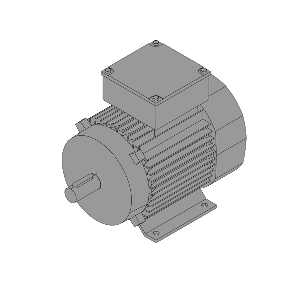
Foot mounted version
Example: DM80G4 – B3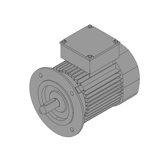
Flange mounted version B5
Example: DM132M4 – B5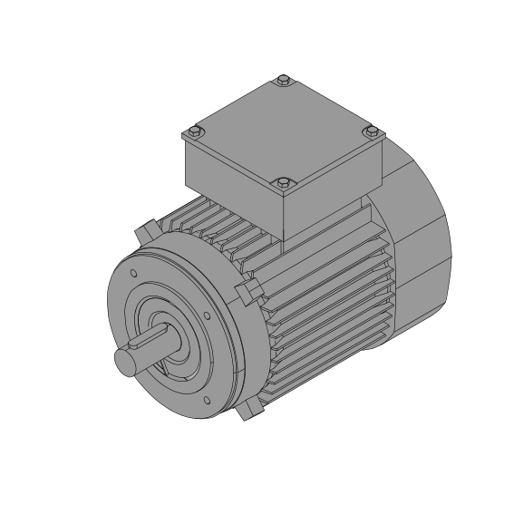
Flange mounted version B14
Example: DM71G6 – B14K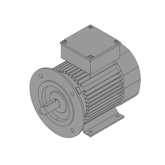
Foot-flange mounted version
Example: DM90S4 – B3/B5
Type designation
- DM
- Range
- 90S
- Frame size
- 4
- Number of poles
- F TW
- Options
-
IE2 - Efficiency class
B_ - Brake
B_MB - Brake with hand release
F - Forced ventilation
EI_ – Incremental encoder
ER_ – Absolute encoder multiturn
TW – PTC thermistor sensor
TS – Thermorelay (closed)
Technical characteristics
The motors correspond to the following standards:
- DIN EN 60034
- Rotating electrical machines, rating and performance.
- IEC60072
- Totally enclosed fan-cooled motors with squirrel cage, fixing dimensions and allocation of rating.
- DIN 42948
- Mounting flanges for electrical machines
- Number of poles: 2 pole, 4 pole, 6 pole, 8 pole, 4/2 pole, 8/2 pole
- Protection standard IP54
- Insulation class 155
- Voltage/Frequency
Δ/Y 230/400V 50Hz 1)
Δ/Y 230/400V 50Hz // Y 460V 60Hz 1)
Δ/Y 400/690 V 50 Hz
Δ/Y 400/690 V 50 Hz // Δ 460V 60Hz
Δ/Y 290/500 V 50Hz (DM63..DM112)
Δ 500V 50Hz (DA132..DA225)
200V 50Hz
1) Standard voltages
Different voltages and frequencies are available.
Options:
- UL-Version
- EE-Version
- CCC-Version
- CEL-Version
- Dust- and water protection IP65
More Motor Options:
- Explosion proof motor in accordance with ATEX, for use in zone 1, 2, 21, or 22
- Flame proof Motor EExd
- motors with noise reduced brake or with double brake
- Backstop RS
- Torque motor
- Single phase motor 230V 50Hz (service capacitor, Steinmetz circuit)
Motor Power Pn
The values given in the tables are valid for the following conditions:
- Duty cycle S1
- Maximum ambient temperature +40°C
- Installation altitude up to 1000m above mean sea level
The available motor power for different conditions is calculated as follows: P=Pn·fs·ft·fn
Factor fs for different duty type
| Duty type | fs | |
| S1 | Continuous duty. Operation with constant load. The motor reaches the thermal equilibrium. | 1.0 |
| S2-10min S2-30min S2-60min |
Short term duty. Operation with constant load followed by a stop. During the stop the motor returns to the ambient temperature. Described by the duration of the load period in min. | 1.4 1.25 1.1 |
| S3-15%ED S3-25%ED S3-40%ED S3-60%ED |
Intermittent periodic duty. Operation with a sequence of identical cycles including a time of operation with constant load and a stop. Described by the cyclic duration factor in %. | 1.4 1.3 1.2 1.1 |
| S4 .. S10 | Intermittent periodic duty. The start or stop phase of the motor is effecting the temperature raise. More data of the duty cycle are necessary. | On request |
Factor ft for different ambient temperature θ
- θ ≤ 40°C : ft=1.0
- 40°C < θ ≤ 50°C : ft=0.87
- 50°C < θ ≤ 60°C : ft=0.75
Factor fh for different altitude h
- h ≤ 1000m : fh=1.0
- 1000m < h ≤ 2000m : fh=0.9
- 2000m < h ≤ 3000m : fh=0.8
- 3000m < h ≤ 4000m : fh=0.7
- 4000m < h ≤ 5000m : fh=0.6
Permissible Radial Forces for the Output Shaft
| FR1 [N] | |||||||
| Motor | Output shaft dxl [mm] |
K1 [mm] |
3000 rpm |
1500 rpm |
1000 rpm |
750 rpm |
|
| DM63 | 11x23 | 155.5 | 430 | 540 | 620 | 680 | |
| DM71 | 14x30 | 176 | 420 | 530 | 610 | 670 | |
| DM80 | 19x40 | 200 | 700 | 880 | 1010 | 1110 | |
| DM90 | 24x50 | 217 | 750 | 950 | 1080 | 1190 | |
| DM100 | 28x60 | 275 | 1050 | 1330 | 1520 | 1670 | |
| DM112 | 28x60 | 286 | 1520 | 1920 | 2190 | 2410 | |
| DM132 | 38x80 | 438 | 2140 | 2730 | 3130 | 3460 | |
| DM160 | 42x110 | 558 | 2680 | 3410 | 3930 | 4330 | |
| DA180 | 48x110 | 495 | 1870 | 2360 | 2060 | 2970 | |
| DA200 | 55x110 | 590.5 | 2820 | 3550 | 4070 | 4480 | |
| DA225 | 60x140 | 665.5 | 4910 | 6190 | 7090 | 7800 | |
For selection condition formulas, see page: Permissible Radial Forces for the Output Shaft
Bearing Types Used (Standard version)
| Motor | D - Bearing | ND - Bearing |
| DM63 | 6202-2Z | 6202-2Z |
| DM71 | 6202-2Z | 6202-2Z |
| DM80 | 6204-2Z | 6204-2Z |
| DM80GD DM90 | 6205-2Z | 6205-2Z |
| DM90SD DM90LB DM100 | 6206-2Z | 6206-2Z |
| DM100LA DM100LF DM112 | 6306-2Z | 6306-2Z |
| DM132 | 6308-2Z | 6308-2Z |
| DM160 | 6309-2Z | 6309-2Z |
| DA180 DA200 | 6212-2Z | 6212-2Z |
| DA225S | 6313-2Z | 6212-2Z |
| DA225M | 6313-2Z | 6313-2Z |